DIY eboard for the forum

Programming Topics (Computer Chess) and technical aspects as test techniques, book building, program tuning etc

Moderator: Andres Valverde

DIY eboard for the forum

Postby Revolt » 18 Jan 2015, 18:43

Hi all:
I am a 40 yr chess veteran and MIT certified in Electronic design.
I am hoping to develop a lower cost e-board for general use. Perhaps in the sub $300 range,retail. :idea:
It is a personal project. :!:

I am looking for support from the forum if possible as communications between a PC chess programme and an eboard are new to me.

As I understand it so far...Chess programmes produce PGN in a window which is translated by a DLL or helper app. into a serial communication via RS232 over usb or direct USB to the eboard which supports bidirectional comms providing for player moves to be fed back to the PC as PGN.

If this is so, I would need a to setup a testbed (Windows 7 for now)that I can use as a means to evaluate bidirectional PGN communications with the e board prototype. I need suggestions for which Chess software to use in the testbed as well as any helper apps to do the PGN comms.

On the hardware side, I am developing on a Microchip 8 bit platform in either C or ASM. Chess piece identification via magnetic or RFID tags and RGB LED feedback in each square to provide for maximum functionality. Dual Chess clock capability to be added later. Eboard capabilities to enhance PvP play with PGN archiving, upload/download and playback, Fischer chess setup capable and new player training aids such as chess piece move range display and color coded LEDs showing the last few opponent moves as a handicap. The magnetic /RF tag on each chess piece base can be removed and applied to new pieces to permit chess piece upgrades.
Board design to permit hardwood/glass/marble/porcelain upgrades within the 8x8, 1/16" acrylic grid. RGB colors to be displayed via the grid, not the squares.

Prototype board will be a travel sized 12" x 12". I want to make this build available to the forum at cost. (hopefully <$125 ea).

Thanks for any support....esp. windows DLL dev. and PGN bidirectional comms. 8-)
Ancel
Revolt
 
Posts: 20
Joined: 17 Jan 2015, 19:41

Re: DIY eboard for the forum

Postby H.G.Muller » 18 Jan 2015, 21:56

Revolt wrote:As I understand it so far...Chess programmes produce PGN in a window which is translated by a DLL or helper app. into a serial communication via RS232 over usb or direct USB to the eboard which supports bidirectional comms providing for player moves to be fed back to the PC as PGN.


It depends on what you mean by "Chess programmes", and would probably be wrong no matter what.

Chess software can be roughly devided into engines (which embody the AI responsible for thinking up moves) and GUIs (which display a Chess board image, and allow the user to enter moves by dragging around pieces on it through the mouse). They communicate through pipes set up by the GUI; as far as the engine is concerned it is just a console application that accepts moves and prints them as text, on its standard input and output. The format of this communication is not PGN, but a protocol like CECP (WB protocol) or UCI.

GUIs typically implement functions like saving a game that has just been played on a file (in PGN format) controlling the parameters of the engine (e.g. time per move, memory and CPU use).

Sensory boards will require driver software, usually supplied by the board manufacturer as DLL, and usually this interfaces with the GUI. The GUI can have a separate 'channel' for that, linking to the DLL directly. In this case it would have to be aware of what services the DLL contains. Which might be different for board of different manufacturers.

So it is more convenient to disguise the board as an engine (a so-called pseudo-engine). After all, the board is just a device to accept and generate chess moves, and to the GUI it is of no importance if the intelligence deciding upon the moves is silicon or carbon-based. Then, if someone wants to play against an engine through the board, he just starts a game in the GUI between the board pseudo-engine and the real engine.
User avatar
H.G.Muller
 
Posts: 3453
Joined: 16 Nov 2005, 12:02
Location: Diemen, NL

Re: DIY eboard for the forum

Postby Revolt » 18 Jan 2015, 23:16

So it is more convenient to disguise the board as an engine (a so-called pseudo-engine).


Hi ,
can you elaborate on this for me....?

I am still not clear on how to go about extracting the move info...eg E2 - E4, and also inserting a move eg E7- E5 from/to the chess engine's ascii interface. This is my main challenge at the moment.

Also, is there a chess engine that makes this available natively for serial I/O?

This site seems to have some clues as to what is going on.
http://www.tim-mann.org/extensions.html
Revolt
 
Posts: 20
Joined: 17 Jan 2015, 19:41

Re: DIY eboard for the forum

Postby H.G.Muller » 19 Jan 2015, 10:03

Revolt wrote:
So it is more convenient to disguise the board as an engine (a so-called pseudo-engine).


Hi ,
can you elaborate on this for me....?

I am still not clear on how to go about extracting the move info...eg E2 - E4, and also inserting a move eg E7- E5 from/to the chess engine's ascii interface. This is my main challenge at the moment.

A description of WB protocol can be found at http://hgm.nubati.net/newspecs.html . This describes in detail how engines communicate with the GUI, for their moves as well as for other aspects of their functioning (which might not me relevant at all for a sensory board).


Also, is there a chess engine that makes this available natively for serial I/O?

I am not sure what you are asking here. You mean over a COM port? I don't know of any engine that would do that. But of course I am only interested in engines that I can run under WinBoard, so what else an engine could do could easily have escaped me, as I have no application for it. But why would an engine ever do such a thing?

I know about a (no longer supported) RS-232 interface of the ChessBase GUI, which could be used to play two engines on different PCs against each other. By running one engine under that GUI on each computer, and connecting the GUIs to relay the moves. There was WinBoard support for this protocol in the form of a WB232 connection adapter, which was a pseudo-engine that then relayed the moves over RS232 to the ChessBase GUI, using this standard. It is now considered obsolete, as nowadays computers are connected by default to the internet, not through COM ports and cables. So there are TCP/IP-based solutions to connect GUIs or engines on different machines.

This site seems to have some clues as to what is going on.
http://www.tim-mann.org/extensions.html

Indeed. Beware, though, dat the last update of this site might have been in 2002. But you can see that most drivers take the form af a pseudo-engine. This has the advantage that the board is automatically usable with any GUI that supports the protocol used by the engine. (So basically everyone if you use one of the common protocols.)

The alternative would be to implement the driver in a GUI. Then the board can only be used wth that GUI, and to do it you would need acces to the source code of that GUI. Which obviously limits your choice. The advantage is that you could do more, as the standard protocol might not offer all funtionality needed for a board, as it is designed for engines).
User avatar
H.G.Muller
 
Posts: 3453
Joined: 16 Nov 2005, 12:02
Location: Diemen, NL

Re: DIY eboard for the forum

Postby Reinhard Scharnagl » 19 Jan 2015, 11:38

Why not develop something really new? 8x8 and 10x8 chess is the future!

Image
Reinhard Scharnagl
 
Posts: 608
Joined: 01 Oct 2004, 08:36
Location: Klein-Gerau, Germany

Re: DIY eboard for the forum

Postby H.G.Muller » 19 Jan 2015, 12:45

It would certainly be nice if the electronics and software were designed to handle larger boards (e.g. upto 12x12). For Shogi it would be nice if the board could detect the orientation of the pieces, as well as their identity. I am not sure how this could be done, however.

What system will be used to detect the pieces anyway? Will there be an LC circuit in every piece with a pick-up loop at the base, and sender and receiver loops in the square? I imagine you could wire all the sender loops along the board files in series, and all receiver loops along ranks, rather than having fully independent sender/receiver pairs in every square. One way to detect orientation of Shogi pieces would be to have two receiver loops in each square, one in the upper half and one in the lower half, and mount the pickup coil for the LC circuit asymmetrically in the Shogi piece.

What suggests itself is to have a circular loop as sender coil under each square, covering the complete square, and a figure-eight coil on top of it as receiver. This would fully decouple the sender and receiver coil in absence of any disturbances on the square. The pieces could then get a pick-up coil that is just over one loop of the figure eight. The polarity of the induced voltage would then reveal whether the piece covers the upper or the lower loop of the receiver coil.

[Edit] Since you are into electronicss design, could you give your opinion on the chances that the following would work? In stead of putting an LC circuit in each piece (which is a bit of a pain), we put an LC circuit under each square, putting all circuits in one board file in series. Simple wire coils overlapping them are put in series rank wise. To read out the board, an rf current is sent through a single rank, driving the LC circuits on it; the response of the latter is detected along the rows. All the squares have the same resonance frequency when empty. Now we glue patches of aluminum foil to the bottom of the pieces, shielding the magnetic flux, thus altering the inductace, detuning the resonances by an amout depending on the piece type (as the surface area of the patches differs per piece type). As the resonators are probably low Q, the readout would consist of driving the rank with a frequency sweep, and measuring at which frequencies the various files give maximum response, and then repeating the procedure for the next rank, etc.
User avatar
H.G.Muller
 
Posts: 3453
Joined: 16 Nov 2005, 12:02
Location: Diemen, NL

Re: DIY eboard for the forum

Postby Reinhard Scharnagl » 19 Jan 2015, 16:33

H.G.Muller wrote:... I am not sure how this could be done, however. ...


Well, I think of a screen camera, which is analysing its view on a chess board.
All pieces might be placed and moved by a viewing human operator.
Reinhard Scharnagl
 
Posts: 608
Joined: 01 Oct 2004, 08:36
Location: Klein-Gerau, Germany

Re: DIY eboard for the forum

Postby H.G.Muller » 19 Jan 2015, 17:34

I discussed the camera idea once with someone working at DGT, and he told me it has been tried, and was not sufficiently reliable. This was for Chess, however. For Shogi, where pieces are basically flat tiles that do not cast shadows on each other, it might be a workable solution. It basically comes down to recognizing written kanji from a set of 14. (Times 2 if you consider upside-down kanji different. But the outline of the tile can probably be recognized independnetly, and will tell the orientation of the kanji that must be identified.
User avatar
H.G.Muller
 
Posts: 3453
Joined: 16 Nov 2005, 12:02
Location: Diemen, NL

Re: DIY eboard for the forum

Postby Reinhard Scharnagl » 19 Jan 2015, 19:46

Maybe they awaited too much. There is no need to interprete the whole board,
it might be sufficient to detect the changes between two situations evolving
from a well defined starting array.
Reinhard Scharnagl
 
Posts: 608
Joined: 01 Oct 2004, 08:36
Location: Klein-Gerau, Germany

Re: DIY eboard for the forum

Postby H.G.Muller » 19 Jan 2015, 20:21

The design goal of the DGT board is that the user can set up an arbitrary position from scratch, and that the board then recognizes it. This is why all the pieces have circuits in them with different resonance frequencies, so that they can be recognized. The differential update that you propose would indeed be much simpler, both for a camera and for a sensory board. Only promotions would still be a problem.
User avatar
H.G.Muller
 
Posts: 3453
Joined: 16 Nov 2005, 12:02
Location: Diemen, NL

Re: DIY eboard for the forum

Postby Revolt » 20 Jan 2015, 18:04

Well, I don't do Apps for the PC....or Tablets..so my challenge is how to access the ascii moves, eg d2-d4 from winboard. The move history only shows the last position, not the origin.
Can anyone advise or provide support to dev. an applet to perhaps write winboard's moves into perhaps notepad or terminal? I can grab it from there and do the e board comms.

Inputting piece moves (human) seems easier as it has a keyboard interface that can be supplied with the ascii moves.
I want to use simpler open source as much as possible....so AutoHotkey or AutoIt scripting is what I am looking at to grab the moves from winboard and Tx them to the e-board. Preferably rs232 serial over usb at first. Then usb-usb to cater for tablets.
I'd be pleased to incorporate forum suggestions into making this project worthwhile and cost effective.
I can look at doing bigger boards as suggested but first things first.

On the HW side, I have a means to calibrate the gauss of neodymium mags (it's easily sharable & DIY cheap once I document it) ...so that's the basis of the piece recognition using linear hall effect sensors. I plan to make a transferable ident. 'base' so folks can use their own choice of chess pieces.
Revolt
 
Posts: 20
Joined: 17 Jan 2015, 19:41

Re: DIY eboard for the forum

Postby Revolt » 20 Jan 2015, 18:15

H.G.Muller wrote:[Edit] Since you are into electronicss design, could you give your opinion on the chances that the following would work? In stead of putting an LC circuit in each piece (which is a bit of a pain), we put an LC circuit under each square, putting all circuits in one board file in series. Simple wire coils overlapping them are put in series rank wise. To read out the board, an rf current is sent through a single rank, driving the LC circuits on it; the response of the latter is detected along the rows. All the squares have the same resonance frequency when empty. Now we glue patches of aluminum foil to the bottom of the pieces, shielding the magnetic flux, thus altering the inductace, detuning the resonances by an amout depending on the piece type (as the surface area of the patches differs per piece type). As the resonators are probably low Q, the readout would consist of driving the rank with a frequency sweep, and measuring at which frequencies the various files give maximum response, and then repeating the procedure for the next rank, etc.


While this is RF approach is possible..DGT has filed patents which I don't want to infringe...or even create a chance for litigation...so i am going magnetic as I mentioned.
BTW aluminium will not block a magnetic flux, nor even an electric field unless it's grounded or configured as a faraday cage. Low Q isn't good if you want to differentiate signal frequencies based on amplitude.
The easier approach might be to include soft iron 'cores' in the pieces so that they change the resonant frequency of the coils in the board driven by a colpitts oscillator . Thus the size of the core and proximity to the coil inductor differentiates the pieces. A NE567 PLL frequency detector array or a spectrum analyzer app in a microcontroller would separate the frequencies.
Revolt
 
Posts: 20
Joined: 17 Jan 2015, 19:41

Re: DIY eboard for the forum

Postby H.G.Muller » 20 Jan 2015, 20:17

Revolt wrote:While this is RF approach is possible..DGT has filed patents which I don't want to infringe...or even create a chance for litigation...so i am going magnetic as I mentioned.

Well, that is up to you, of course. But I have looked at the DGT patent, and I am confident that it does not cover what I have in mind.

BTW aluminium will not block a magnetic flux, ...

Sure it will. If it is an rf field. Time-dependent magnetic fields will induce currents in a conductor, which oppose the field. The field can only penetrate once the induced currents have decayed by Ohmic resistance of the conductor, so that it essentially has to diffuse into the conductor. At high frequency this takes way too long, as aluminum is a very good conductor. In a super-conductor the field would be screened forever (Meissner effect), as the induced current would never decay.

This is, for instance, how metal detectors work. Conducting objects under ground change the inductance of the detection loop, and the shift in resonance frequency is easily detected.

nor even an electric field unless it's grounded or configured as a faraday cage. Low Q isn't good if you want to differentiate signal frequencies based on amplitude.

Well, when I said "low Q" I had something like 10 in mind, as opposed to 1000. That should be good enough to distinguish 12 different pieces, if you can spread out the resonances over a factor 2 frequency range. I have no idea how high a Q could be, from a simple wire-loop coil etched and a standard ceramic capacitor. The only unavodable losses seem to be radiative losses, and they are probably small if the corresponding wavelength is very large compared to the size of the coil.

Note that phase shift might be a more accurate way to detect the resonance frequency than amplitude. As the driving frequency is available, it should be possible to derive a phase signal by mixing it with the response signal in some quadrature detector.

The easier approach might be to include soft iron 'cores' in the pieces so that they change the resonant frequency of the coils in the board driven by a colpitts oscillator . Thus the size of the core and proximity to the coil inductor differentiates the pieces. A NE567 PLL frequency detector array or a spectrum analyzer app in a microcontroller would separate the frequencies.

That would indeed be an alternative to detune the resonances (although I would be inclined to use ferrite rather than soft iron). Just gluing a conducting sticker to the bottom of the pieces seemed a lot cheaper, though. In fact the whole thing could be dirt cheap: just a printed circuit board the size of the chess board, in which all the coils are etched (and on which the thin wood slabs making the squares are glued), with 64 capacitors mounted on it on the bottom side to make the resonant circuits. A micro-controller with 8 output ports could drive the resonant circuits, and 8 rf demodulation chips could detect the resonances and feed them back to micro-controller input ports.
User avatar
H.G.Muller
 
Posts: 3453
Joined: 16 Nov 2005, 12:02
Location: Diemen, NL

Re: DIY eboard for the forum

Postby H.G.Muller » 20 Jan 2015, 20:30

Revolt wrote:Well, I don't do Apps for the PC....or Tablets..so my challenge is how to access the ascii moves, eg d2-d4 from winboard. The move history only shows the last position, not the origin.
Can anyone advise or provide support to dev. an applet to perhaps write winboard's moves into perhaps notepad or terminal? I can grab it from there and do the e board comms.

Inputting piece moves (human) seems easier as it has a keyboard interface that can be supplied with the ascii moves.
I want to use simpler open source as much as possible....so AutoHotkey or AutoIt scripting is what I am looking at to grab the moves from winboard and Tx them to the e-board. Preferably rs232 serial over usb at first. Then usb-usb to cater for tablets.
I'd be pleased to incorporate forum suggestions into making this project worthwhile and cost effective.
I can look at doing bigger boards as suggested but first things first.

I must say that this all sounds so strange to me that I can hardly imagine how exactly you want to do this. My first impression is that you want to make something that is reasonably simple several orders of magnitude more difficult by doing it in an extremely cumbersome way. Especially your statement "I don't do Apps for the PC" worries me. I don't think it would be possible to get anything to work without some amount of programming on the PC.
User avatar
H.G.Muller
 
Posts: 3453
Joined: 16 Nov 2005, 12:02
Location: Diemen, NL

Re: DIY eboard for the forum

Postby Revolt » 20 Jan 2015, 21:51

Ok I looked at this:
http://www.open-aurec.com/wbforum/viewt ... 24&t=51739

And I can't hope to use it as i have to learn too much just to understand...I don't have the time to invest.
My strengths lie elsewhere; hardware and microcontrollers and prototyping electronics.

If H.G. Muller could be so kind as to help with providing the interface from Winboard to Transmit (rs232 over usb) the 4 or 5 character coordinate move and RX the 4 character Eboard move that would allow me to expedite this project. Being an open source effort, it is for the good of all.
I expect to eventually create 'kits' to make the build simple for those who don't have the time to do 100% DIY.
Revolt
 
Posts: 20
Joined: 17 Jan 2015, 19:41

Re: DIY eboard for the forum

Postby H.G.Muller » 20 Jan 2015, 23:56

You should think more about what information to send over the USB/RS232 line. Moves alone are not enough to make the board useful to anyone. It should also be possible for the board to send positions, (after the user set up a new one), indicate that pieces have been dropped onto the board, or that moves have been taken back. And that the game is finished, and how. DGT boards define various manipulations that are used to make the board emit signals, like lifting the King and putting it back on the same square to indicate a new position has been set up and is ready, and whether the computer should start to play white or black. Placing two Kings next to each other in the center on white, black or differently colored squares to indicate 1-0, 0-1 or 1/2-1/2, etc.

It would also be nice if the board could generate a signal to switch the engine to analysis mode, to exclude or include moves from analysis, (so you can ask for a second-best move), ask for a hint.

It would probably be better to just send low-level board modifications over the line, i.e. messages that indicate a square was evacuated, or whether a new piece appears on a square. The driver software on the PC can then decide from that whether it is a move, a takeback, an agreed-upon signal... Doing that in the micro-controller just makes the whole thing inflexible, and thus less capable and less useful. In the other direction it could just send codes to light up individual LEDs, in a specified color.
User avatar
H.G.Muller
 
Posts: 3453
Joined: 16 Nov 2005, 12:02
Location: Diemen, NL

Re: DIY eboard for the forum

Postby Revolt » 21 Jan 2015, 01:18

H.G.Muller wrote:You should think more about what information to send over the USB/RS232 line. Moves alone are not enough to make the board useful to anyone. It should also be possible for the board to send positions, (after the user set up a new one), indicate that pieces have been dropped onto the board, or that moves have been taken back. And that the game is finished, and how. DGT boards define various manipulations that are used to make the board emit signals, like lifting the King and putting it back on the same square to indicate a new position has been set up and is ready, and whether the computer should start to play white or black. Placing two Kings next to each other in the center on white, black or differently colored squares to indicate 1-0, 0-1 or 1/2-1/2, etc.

It would also be nice if the board could generate a signal to switch the engine to analysis mode, to exclude or include moves from analysis, (so you can ask for a second-best move), ask for a hint.

It would probably be better to just send low-level board modifications over the line, i.e. messages that indicate a square was evacuated, or whether a new piece appears on a square. The driver software on the PC can then decide from that whether it is a move, a takeback, an agreed-upon signal... Doing that in the micro-controller just makes the whole thing inflexible, and thus less capable and less useful. In the other direction it could just send codes to light up individual LEDs, in a specified color.


I quite agree, but if I cannot establish I/O this is a nonstarter project. I am beginning to think this is going to take up too much of my time just to figure out the I/O and establish it. Learning a whole new language and API isn't on the cards for me. :shock:
I can't even get Winboard to show the full move coordinates in the play history ...seems there is no way. I had a look at the winboard.debug engine comm file....I can see the coordinate moves mixed in with a lot of other comms.

Perhaps I can just create the smart E board design and a protocol to mimic the DGT feature sets and someone else can do the PC side interface.. I can't do the interface it seems. :(

Would you be willing to help in this regard? Some type of joint approach? :idea:

It does seem that creating a 'shell' engine to comm. with winboard and then the rs232 eboard for bidrectional comms is the way to go.....That way the eboard can instruct winboard using winboard's command set as well as send moves.

BTW I am installing Visual Studio 2013 now....maybe its time to learn C++ for the desktop...but it'll take a while.
Revolt
 
Posts: 20
Joined: 17 Jan 2015, 19:41

Re: DIY eboard for the forum

Postby H.G.Muller » 21 Jan 2015, 10:33

A joint approach would make sense. The project cannot work without having some specially designed software on the PC, and if you don't have any expertise there, you should 'outsource' it, and not try to affect the design of that part. There once was this brilliant physicis who had invented an engine that worked on nothing but sea water, and when he then wanted to design a car based on it, said "but it should not have any wheels, because I don't know anything about those". So he insisted that the one manufacturing the undercarriage used pogo sticks instead. Well, it came to nothing, despite the free fuel...

I am sure I will be able to write a PC program that communicates over a COM port, and interfaces with WinBoard (or any other GUI) as an engine. In about 30 minutes. It is just a matter of defining first what it should send to the COM port.

The whole process of sensing moves through the board will neccessarily involve some cleverness, so distinguish real moves from false signals when someone slides a Rook over the board, or puts it down halfway between squares and then corrects, etc. It is a design choice whether you want this implemented in the micro-controllwer or in the PC driver. And this greatly affects what sort of information would have to be sent over the USB/RS232 connection.

So we first should agree on what information would be sent in either direction over the cable, and how that information would be encoded.

Personally I would put as much of the intelligence of the system on the PC side rather than in the micro-controller. Just because it seems more flexible. Changing the software / firmware on the micro-controller seems much more difficult than changing the driver.
User avatar
H.G.Muller
 
Posts: 3453
Joined: 16 Nov 2005, 12:02
Location: Diemen, NL

Re: DIY eboard for the forum-progress!

Postby Revolt » 21 Jan 2015, 14:38

Thanks for the support , your 30 minutes is probably worth at least 100 hours on my end. :mrgreen:
For managing the improper placement of the pieces, the board will 'know' that you picked up a particular piece and will 'know' when you put it down if it is seen as the same piece. If the piece is not detected as the same the board can complain via a beep or an led flash/color to insist that you sort it out before the board transmits the coords to winboard. The driver/ winboard can decide if it was a simple move, a capture or a move/promotion.
It is reasonable to consider adding in a unique 'control' piece...which can send commands to winboard (by placing on different squares) to control the play setup. The board can acknowledge the custom control piece with an LED or beep response.

I'd want to have a dual game clock option down the road so we'd need to have a means to handle those comms. Building in a simple custom ASCII instruction set into the eboard to give the driver direct control over the board's LEDS/beeper and chess piece layout should place the maximum intelligence in the driver. The driver can also interpret the custom command sent by the eboard (by using the 'control' piece) to respond however is necessary.

The custom chess piece layout/setup can be communicated to the user via flashing an LED color associated with a chess piece on a grid square, once the correct piece is detected the sequence continues until the board is setup as per winboard/driver requirements. I imagine it can be done in the reverse so that the user sets up the board with the pieces and then sends that data to winboard with a 'control' piece command (such as 3 taps on any grid square)

Since you have massively more experience than I do in the world of computer/online chess I'd hope you could layout what you'd want to see as features or flexibility and we could then work out where the features will lie, in the driver or in the eboard.

The first e board prototype will be 12"x12" as I have that size PCB on hand right now.

I appreciate and look forward to the combined effort. :!:
Revolt
 
Posts: 20
Joined: 17 Jan 2015, 19:41

Re: DIY eboard for the forum

Postby H.G.Muller » 21 Jan 2015, 15:50

OK, sounds good. Having a separate control piece is probably not needed, as there are plenty of otherwise impossible actions that could be used to generate signals. Tapping on any square with the King is for instance always possible.

I will give it some thinking what signals would be needed.

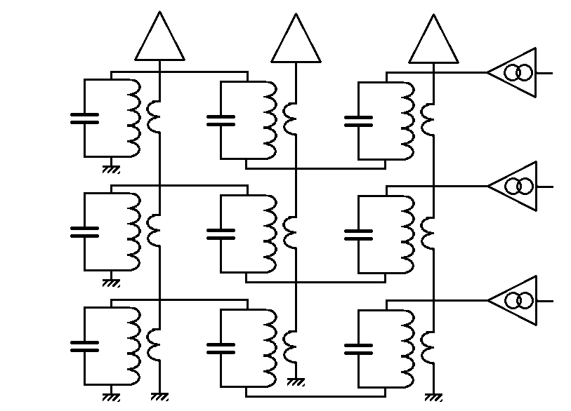
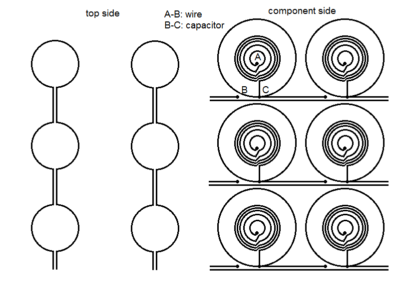
In the mean time I have been day-dreaming a bit on a sensory board based on the multiplexed metal-detector design:

Image
circuit diagram

Image
printed circuit board

The main question regarding feasibility here is how large the Q-factor can be of a simple coil of a few windings etched in a PCB, plus a capacitor. This determines if it can be detured in enough recognizably different ways by the proximity of a metal marker on a piece. I see no way to get this info other than trying it out.
User avatar
H.G.Muller
 
Posts: 3453
Joined: 16 Nov 2005, 12:02
Location: Diemen, NL

Next

Return to Programming and Technical Discussions

Who is online

Users browsing this forum: No registered users and 7 guests